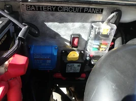
So, I’ve noticed the OEM accessory busbar battery (middle) terminal is fed by a W/R conductor that appears to be a 20AWG.
And a lot of the aftermarket accessory vendor’s instructions connect to the battery terminal.
I’m concerned about overloading that conductor, so I ordered (3) Eaton two-post busbars and plan to split the three OEM terminals onto separate busbars. I’ll abandon the OEM W/R batt conductor and run a 12AWG (or 10) conductor directly from the battery with an inline 30A fuse at the batt.
I would have (8) accessory & OEM conductors landing on the ignition terminal, at least four on the battery terminal, and (7) ground conductors on the ground terminal. Stacking all those ring terminals ain’t gonna work on the single OEM terminals.
I’m guessing a lot of those conductors are either relay triggers or switch lighting and don’t pull much. I’ve reached out to the various manufacturers to find out the function and draw for the various conductors. We’ll see if I get any responses.
I’ll post a pic when I get finished.
And a lot of the aftermarket accessory vendor’s instructions connect to the battery terminal.
I’m concerned about overloading that conductor, so I ordered (3) Eaton two-post busbars and plan to split the three OEM terminals onto separate busbars. I’ll abandon the OEM W/R batt conductor and run a 12AWG (or 10) conductor directly from the battery with an inline 30A fuse at the batt.
I would have (8) accessory & OEM conductors landing on the ignition terminal, at least four on the battery terminal, and (7) ground conductors on the ground terminal. Stacking all those ring terminals ain’t gonna work on the single OEM terminals.
I’m guessing a lot of those conductors are either relay triggers or switch lighting and don’t pull much. I’ve reached out to the various manufacturers to find out the function and draw for the various conductors. We’ll see if I get any responses.
I’ll post a pic when I get finished.